16-bit shift register module using 74HC595 controlled using Arduino UNO
Here, we will see the circuit to interface a 16-bit serial-in parallel-out Shift register module using Arduino UNO. Shift register module is powered from Arduino UNO.
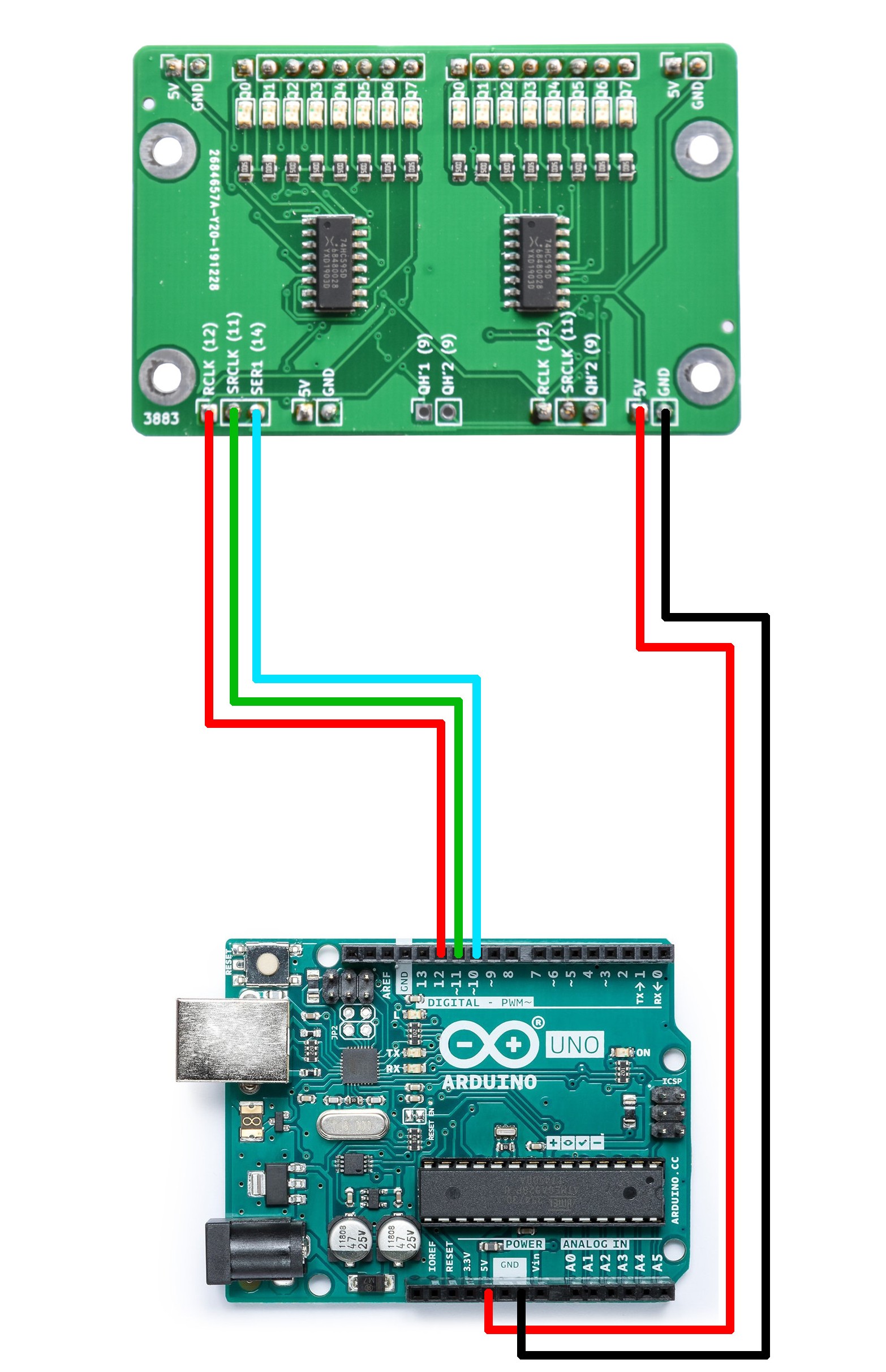
This module will help to create 16 digital outputs from only 3 digital pins of Arduino. Purchase the module from this purchase link. This module can be used in applications where more digital outputs are required such as LED cube, LED matrix etc. Purchase module from the following link.
Purchase link
Upload the following program to Arduino UNO. Change the value in customDelay() function to change the speed of running LED.
This module will help to create 16 digital outputs from only 3 digital pins of Arduino. Purchase the module from this purchase link. This module can be used in applications where more digital outputs are required such as LED cube, LED matrix etc. Purchase module from the following link.
Purchase link

Upload the following program to Arduino UNO. Change the value in customDelay() function to change the speed of running LED.
/*
  Shift Register Example
  Turning on the outputs of a 74HC595 using an array

 Hardware:
 * 74HC595 shift register
 * LEDs attached to each of the outputs of the shift register

 */
//Pin connected to ST_CP (12) of 74HC595
int latchPin = 12;
//Pin connected to SH_CP (11) of 74HC595
int clockPin = 11;
////Pin connected to DS (14) of 74HC595
int dataPin = 10;

//holders for information you're going to pass to shifting function
byte data;
byte dataArray[10];

void customDelay() {
  delayMicroseconds(1000);
}

void setup() {
  //set pins to output because they are addressed in the main loop
  pinMode(latchPin, OUTPUT);
  pinMode(clockPin, OUTPUT);
  pinMode(dataPin, OUTPUT);
  Serial.begin(9600);

  //Binary notation as comment
  dataArray[0] = 0xFF; //0b11111111
  dataArray[1] = 0xFE; //0b11111110
  dataArray[2] = 0xFC; //0b11111100
  dataArray[3] = 0xF8; //0b11111000
  dataArray[4] = 0xF0; //0b11110000
  dataArray[5] = 0xE0; //0b11100000
  dataArray[6] = 0xC0; //0b11000000
  dataArray[7] = 0x80; //0b10000000
  dataArray[8] = 0x00; //0b00000000
  dataArray[9] = 0xE0; //0b11100000
}

void loop() {
  for (int j = 0; j < 9; j++) {
    //load the light sequence you want from array
    data = dataArray[j];
    //ground latchPin and hold low for as long as you are transmitting
    digitalWrite(latchPin, 0);
    customDelay();
    //move 'em out
    shiftOut(dataPin, clockPin, data);
    shiftOut(dataPin, clockPin, data);

    //return the latch pin high to signal chip that it
    //no longer needs to listen for information
    digitalWrite(latchPin, 1);
    customDelay();
    delay(50);
  }
}

// the heart of the program
void shiftOut(int myDataPin, int myClockPin, byte myDataOut) {
  // This shifts 8 bits out MSB first,
  //on the rising edge of the clock,
  //clock idles low

  //internal function setup
  int i=0;
  int pinState;
  pinMode(myClockPin, OUTPUT);
  pinMode(myDataPin, OUTPUT);

  //clear everything out just in case to
  //prepare shift register for bit shifting
  digitalWrite(myDataPin, 0);
  customDelay();
  digitalWrite(myClockPin, 0);
  customDelay();

  //for each bit in the byte myDataOut
  //NOTICE THAT WE ARE COUNTING DOWN in our for loop
  //This means that %00000001 or "1" will go through such
  //that it will be pin Q0 that lights.
  for (i=7; i>=0; i--)  {
    digitalWrite(myClockPin, 0);
    customDelay();

    //if the value passed to myDataOut and a bitmask result
    // true then... so if we are at i=6 and our value is
    // %11010100 it would the code compares it to %01000000
    // and proceeds to set pinState to 1.
    if ( myDataOut & (1<<i) ) {
      pinState= 1;
    }
    else {
      pinState= 0;
    }

    //Sets the pin to HIGH or LOW depending on pinState
    digitalWrite(myDataPin, pinState);
    customDelay();
    //register shifts bits on upstroke of clock pin
    digitalWrite(myClockPin, 1);
    customDelay();
    //zero the data pin after shift to prevent bleed through
    digitalWrite(myDataPin, 0);
    customDelay();
  }

  //stop shifting
  digitalWrite(myClockPin, 0);
  customDelay();
}